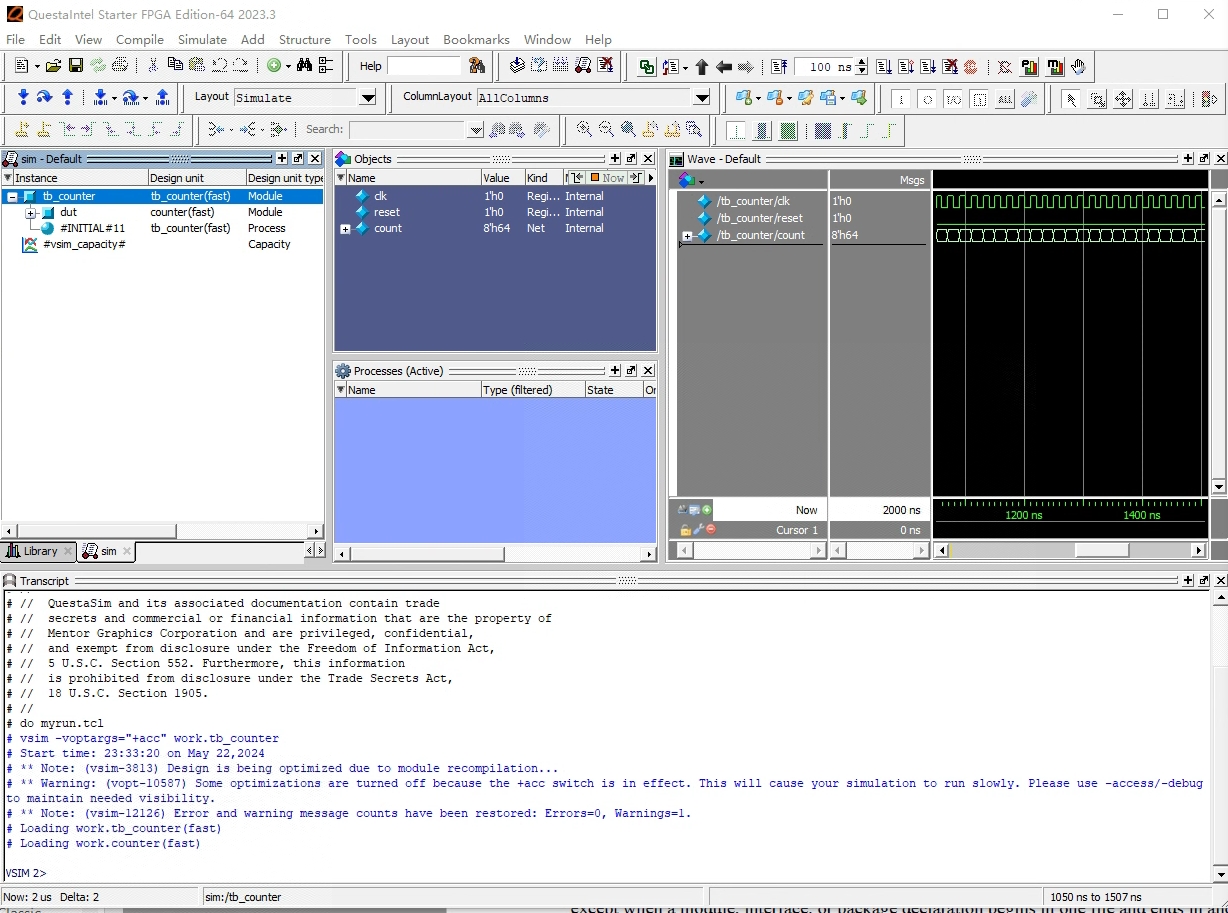
接前面Quartus Prime Lite小记四,已经安装了 Questa Intel FPGA Starter 版本。不妨使用这个版本,简单且认真地了解一下Questa这个仿真软件怎么用...
对于Questa来说,基本的仿真流程如下:
- 编译设计文件(对verilog来说,使用 vlog)
另外,还有一个基于项目的仿真流程:
我们先了解基本的仿真流程
从一个计数器开始?
试着找一个verilog的入门例子,看看能不能仿真起来...

用verilog编写了一个计数器模块,文件名 counter.v:
| module counter(output reg[7:0] count, input wire clk, input wire reset);
always @(posedge clk or posedge reset)
count <= (reset) ? 8'h00 : count + 8'h01;
endmodule
|
或者写成这样:
| module counter(count, clk, reset);
output [7:0] count;
input clk, reset;
reg [7:0] count;
always @(posedge clk or posedge reset)
count <= (reset) ? 8'h00 : count + 8'h01;
endmodule
|
要进行仿真,需要再编写一个testbench文件,比如命名 tb_counter.v
1
2
3
4
5
6
7
8
9
10
11
12
13
14
15
16
17
18
19
20
21
22
23 | `timescale 1ns / 1ns
module test_counter;
reg clk, reset;
wire [7:0] count;
// Instantiate the counter device under test (DUT)
counter dut (count, clk, reset);
// Generate a clock with a period of 20 ns
initial begin
clk = 0;
forever #10 clk = !clk; // Toggle clock every 10 ns
end
// Generate a reset pulse
initial begin
reset = 0; // Initial reset state
#5 reset = 1; // Assert reset after 5 ns
#4 reset = 0; // Deassert reset after 9 ns total
end
endmodule
|
注意:第一行的格式
`timescale <time_unit> / <time_precision>,时间单位用于表明仿真中的1个时间单位对应现实世界中多长时间。
我们可以用questa提供的编译verilog与systemverilog的命令行工具vlog,对上面的代码进行编译:
| vlog counter.v tb_counter.v
|
编译结果在work文件夹内(二进制文件?)
而后使用questa的命令行工具 vsim 启动 questa:
| vsim -voptargs=+acc test_counter work.tb_counter
|
注意,选项-voptargs=+acc`是为了保障信号可见性。(因为我们这个例子跳过了vopt命令,不然,可以给vopt命令传入+acc选项,也可以实现类似效果)。
而后,需要在界面上进行操作,添加wave,并执行run仿真。
规避UI,操作1(.do)?
其实这些UI操作,可以直接合并到前面的命令行中,变成:
| vsim -voptargs=+acc work.tb_counter -do "add wave -position end /tb_counter/*; run 2000"
|
每次这样敲命令太长的话,可以把引号中的内容写入到一个myrun.do文件:
| add wave -position end /tb_counter/*
run 2000
|
而后
| vsim -voptargs=+acc work.tb_counter -do myrun.do
|
注意,生成的波形文件是二进制文件,默认命名 vsim.wlf,可以通过命令行参数来修改它
| vsim -wlf mycounter.wlf -voptargs=+acc work.tb.counter -do myrun.do
|
在Questa中,可以打开这个波形文件进行查看。wlf是 Waveform Logging Format缩写。
这个myrun.do文件,可以继续进行扩展,比如,像下面这样:
1
2
3
4
5
6
7
8
9
10
11
12
13 | vsim tb_counter_opt
add wave count
add wave clk
add wave reset
force -freeze clk 0 0, 1 {50 ns} -r 100
force reset 1
run 100
force reset 0
run 300
force reset 1
run 400
force reset 0
run 200
|
规避UI,操作2(.tcl)?
前面用了 .do文件,其内部是在sim下运行的指令。尽管如此,.do文件其实就是tcl脚本,我们可以在其内部直接使用tcl各种语法。
除了使用do文件,我们可以写成 .tcl 文件,比如 myrun.tcl
| vsim -voptargs=+acc work.tb_counter
add wave -position end /tb_counter/*
#run -all
run 2000
|
通过如下命令执行
vsim 还可以接受一个 `-c` 参数,用它之后,将不会出现UI界面,只能在控制台下仿真。
命令
前面用到两个命令
- vlog:执行verilog或systemverilog的编译
其实也有其他很多命令,比如:
vlib
由于Questa仿真,需要先创建一个library库,而我前面的测试结果是vlog命令执行时会自动创建这个库。网上给的信息与此不太相符,很多信息说vlog不会自动调用vlib,从而...
| vlib work
vlog counter.v tb_counter.v
|
- 先使用 vlib 创建一个库(此处创建一个work的文件夹,其内部有一个
_info文本文件)
- 而后vlog会将编译结果放入到这个库中(默认名字 work)
这个库的名字可以修改的,比如:
| vlib my_test_lib
vlog -work my_test_lib counter.v tb_counter.v
|
vopt
vopt 代表 "Verification Optimization",主要目的是提高仿真效率,从而加快仿真速度。虽然优化可能会使某些内部信号在仿真中不可见(因为它们可能被优化掉了),但通常可以通过特定的选项来保留这些信号,以便于调试。
vlog之后,我们可以执行vopt命令
| vopt +acc tb_counter -o tb_counter_opt
|
而后用 vsim 来对 tb_counter_opt 进行仿真
使用vopt时,完整的脚本 myrun2.tcl 如下:
| vlog *.v
vopt +acc tb_counter -o tb_counter_opt
vsim tb_counter_opt
add wave -position end /tb_counter/*
#run -all
run 2000
|
使用vsim直接执行编译、优化、仿真、添加波形,运行
### 其他
断言
testbench 和 软件开发中的单元测试很像。所以我们不需要界面,直接用断言,也是完全可以的
更新后的tb_counter2.v文件:
 1
 2
 3
 4
 5
 6
 7
 8
 9
10
11
12
13
14
15
16
17
18
19
20
21
22
23
24
25
26
27
28
29
30
31
32
33 | `timescale 1ns / 1ns
module test_counter2;
reg clk, reset;
wire [7:0] count;
// Instantiate the counter device under test (DUT)
counter dut (count, clk, reset);
// Generate a clock with a period of 20 ns
initial begin
clk = 0;
forever #10 clk = !clk; // Toggle clock every 10 ns
end
// Generate a reset pulse
initial begin
reset = 0; // Initial reset state
#5 reset = 1; // Assert reset after 5 ns
#4 reset = 0; // Deassert reset after 9 ns total
#1; // Wait 1 ns to ensure reset propagation
assert(count == 0) else $error("Assertion failed: count is not 0 after reset.");
end
// Assert that count increments correctly after reset
always @(posedge clk) begin
if (!reset) begin
@(posedge clk);
if (count !== count + 1)
$error("Assertion failed: count did not increment correctly.");
end
end
endmodule
|
完全不用界面的话:
| vlib work
vlog counter.v tb_counter2.v
vsim -c -do myrun.tcl
|
用VHDL再走一遍?
用vhdl重写一下前面的verilog计数器,文件名 counter.vhd
1
2
3
4
5
6
7
8
9
10
11
12
13
14
15
16
17
18
19
20
21
22
23
24
25
26
27
28 | library IEEE;
use IEEE.STD_LOGIC_1164.ALL;
use IEEE.NUMERIC_STD.ALL; -- 使用 NUMERIC_STD 来处理数值运算
entity counter is
Port (
count : out STD_LOGIC_VECTOR(7 downto 0);
clk : in STD_LOGIC;
reset : in STD_LOGIC
);
end counter;
architecture Behavioral of counter is
-- 使用 unsigned 类型处理 count_reg 以支持算术运算
signal count_reg: unsigned(7 downto 0) := (others => '0');
begin
process(clk, reset)
begin
if reset = '1' then
count_reg <= (others => '0');
elsif rising_edge(clk) then
count_reg <= count_reg + 1; -- 正确的加法操作
end if;
end process;
-- 将内部的 unsigned 信号转换回 STD_LOGIC_VECTOR 类型输出
count <= std_logic_vector(count_reg);
end Behavioral;
|
这个东西比verilog版本的长太多了...,先跑通再说,有时间再学习VHDL与Verilog的基本语法
由于verilog和vhdl可以并存,我们可以继续使用前面例子中的 testbench 文件进行测试,只需要修改一下tcl脚本 myrun3.tcl:
| vcom counter.vhd
vlog tb_counter.v
vopt +acc tb_counter -o tb_counter_opt
vsim tb_counter_opt
add wave -position end /tb_counter/*
#run -all
run 2000
|
注意vhdl的编译器用的vcom,其他执行起来就和原来一样:
结果
前面提到仿真结果会存放到一个 .wlf 文件中,在Questa中,可以打开这个波形文件进行查看。wlf是 Waveform Logging Format缩写。
另外,我们还可以生成list文件,使用如下命令
| add list -decimal *
write list counter.lst
|
可以得到如下文件 counter.lst:
 1
 2
 3
 4
 5
 6
 7
 8
 9
10
11
12
13
14
15
16
17 | ns /tb_counter/clk
delta /tb_counter/reset
/tb_counter/count
0 +0 1'd0 * ***
0 +1 1'd0 * ***
50 +0 -1'd1 * ***
100 +0 1'd0 * ***
100 +1 1'd0 * ***
150 +0 -1'd1 * ***
150 +2 -1'd1 * ***
200 +0 1'd0 * ***
250 +0 -1'd1 * ***
250 +2 -1'd1 * ***
300 +0 1'd0 * ***
350 +0 -1'd1 * ***
350 +2 -1'd1 * ***
400 +0 1'd0 * ***
|
